


 |
Pulse Input 15KW PWM Servo Amplifier With Position Speed Torque Control Model
Product Details:
| Place of Origin: | China |
| Brand Name: | Vector |
| Certification: | CE |
| Model Number: | VEC-VC-03233H-M-EA |
Payment & Shipping Terms:
| Minimum Order Quantity: | 1 kit |
|---|---|
| Price: | To Be Discussed |
| Packaging Details: | 280*208*78mm,375*290*155mm |
| Delivery Time: | 3-5 work days |
| Payment Terms: | T/T, Western Union, L/C |
| Supply Ability: | 500 kits/month |
|
Detail Information |
|||
| Voltage: | 380V | Power: | 15KW |
|---|---|---|---|
| Phase: | Three Phase | Communication Protocols: | Modbus/EtherCAT/CanOpen |
| Encoder: | 17/23/24 Bit Absolute Encoder | Rated Current: | 32A |
| Input: | Pulse | Control Mode: | Position / Speed / Torque |
| Application: | Robotics/CNC | ||
| Highlight: | Pulse Input PWM Servo Amplifier,15KW PWM Servo Amplifier,15KW PWM Servo Drive |
||
Product Description
PWM Servo Amplifier With Position / Speed / Torque Control Model
Products Description
| Product Name | PWM Servo Amplifier |
| Brand | Vector |
| Model No. | VEC-VC-03233H-M-EA |
| Power4 | 15KW |
| Input | Pulse |
| Voltage | 380V |
| Phase | Three Phase |
| Rated Current | 32A |
| Communication Protocols | Modbus/CANopen/EtherCAT |
| Encoder | 17/23/24 bit absolute encoder |
How is the Servo Drive works? The Location control model, Speed control model and Trogue control model.
| Voltage | Control Mode | Single-phase / three-phase full-controlled rectification SVPWM modulation |
| Encoder | Encoder Feedback | 2500 pulse incremental + Hall encoder; 2500 pulse incremental; 17bit Tamagawa absolute encoder; 23bit Tamagawa absolute encoder; 24bit Nikon absolute encoder; |
| Pulse Command Input | Pulse Type | Differential input,Open collector |
| Frequency Range | Differential input:0-500kHz,pulse width greater than 1us Open collector: 0-300kHz,pulse width greater than 2.5us |
|
| Pulse Mode | pulse + direction; AB pluses; CW+CCW; | |
| DI/DO Interface Type | NPN/PNP | |
| Communication | Modbus/CANopen/EtherCAT | |
| Position Mode | Command Input Method | Pulse Command Internal Planning Position Plan by target position, speed, acceleration and deceleration time Trapezoidal speed curve Cubic speed curve Absolute / relative command mode |
| Instruction Smoothing Mode | Low Pass Filtering / Median Filtering | |
| Electronic Gear Ratio | N/M;(M=1~2147483647,N=1~2147483647) | |
| Torque Limit | Internal Torque Limit / Analog Torque Limit | |
| Feedforward Compensation | Speed Feedforward / Torque Feedforward | |
| Torque Compensation | Fixed Torque Compensation / Analog Torque Compensation / Automatic Torque Compensation; |
|
| Speed Contol Mode | Command Input Type | Pulse Frequency / Analog / Internal Planning Speed |
| Speed Control Range | 1~max speed | |
| Bandwidth | 1kHz | |
| Torque Limit | Internal Torque Limit / Analog Torque Limit | |
| Instruction Smoothing Mode | Low Pass Filtering / Median Filtering | |
| Feedforward Compensation | Torque feedforward | |
| Torque Compensation | Fixed Torque Compensation / Analog Torque Compensation / Automatic Torque Compensation; |
|
| Torque Control Mode | Command Input Type | Internal Torque Reference / Analog Control Torque |
| Torque Compensation | Fixed Torque Compensation / Analog Torque Compensation / Automatic Torque Compensation; |
|
| Speed Limit | Internal Speed Limit / Analog Speed Limit | |
![]()
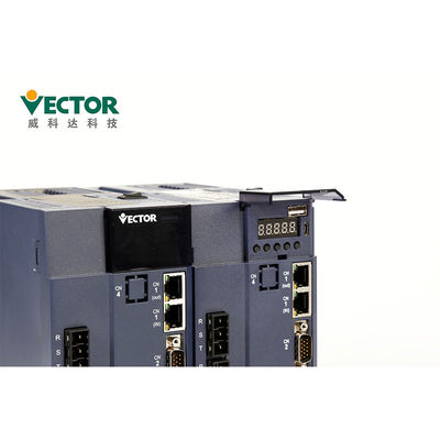
Servo Drive Description- Details about a Servo Drive, how to select the Servo drive model and do installation?
The panel contains 8 buttons and 5 digital tubes. Only 5 of the 8 buttons can be used, and the
remaining 3 buttons reserved. The general functions of the five buttons are shown in the table below.
| Key Name | Key function |
| PAR/ALM | mode switch, return to the previous menu |
| ▲(add) | increase flashing bit value of the LED digital tube |
| ▼(dec) | Decrease flashing digit value of the LED digital tube |
| STOP/RST | Moves the blinking LED tube to the left; checks the high value of data longer than 5 bits; Fault reset;execute Fn function |
| RD/WT | read/write parameter values;enter fn page |
Operating precautions
● in the test operation, in order to prevent accidents, please test the servo motor with no load (not connected to the driver shaft), otherwise it may cause injury.
● when starting to operate on the supporting machine, set the user parameters
that match the machine in advance. If you start operation without parameter setting, it may cause mechanical loss or malfunction.
● to avoid accidents, install a limit switch or a stopper at the end of the movable part of the machine, otherwise it will cause mechanical damage or injury.
● do not make extreme changes to the parameter settings, as this may result in
unstable operation, mechanical damage or injury.
●when the power is turned on or the power supply is cut off, the heat sink of the
servo driver, external braking resistor, motor, etc. may be in a high temperature state. Do not touch it, otherwise it may cause burns.
● when using a servo motor on the vertical axis, set a safety device to prevent the work piece from falling under alarm, over travel, etc. In addition, please perform the servo lock stop setting when an over travel occurs, otherwise the work piece may fall in the over travel condition.
● do not enter the operating range of the machine during operation, otherwise it will cause injury.
● do not touch the servo motor or the movable part of the machine during
operation, otherwise it will cause injury.
● please set up the safety system to ensure safety even in the event of a signal
line breakage. For example, when the positive over travel switch (P-OT) and negative over travel switch (N-OT) signals are disconnected at the factory setting, they operate safely.
● be sure to set the servo OFF state when turning off the power.
● do not turn the power on/off frequently. After the actual operation starts, the
power ON/OFF interval should be more than 1 hour, otherwise the components inside the servo unit will be prematurely aged.
●when an alarm occurs, reset the alarm after the cause is removed and ensure
safety, and restart the operation, otherwise it may cause injury.
● do not use the brake of the brake motor for normal braking, otherwise it may
cause a malfunction.
Certificates
1. CE (EU Safety Standard);
2. IEC/EN61800-5-1:2007 (Safety requirements for electrical, thermal and energy in Section 5-1 of
the variable speed electric driver system), corresponding to the national standard GB12668.501-2013;
3, IEC / EN61800-3: 2004 + A1 (speed control electric driver system part 3 electromagnetic compatibility
standards and its specific test methods), corresponding to the national standard GB12668.3-2012.
![]()
Quality Checking:
Four times Production testing
Two Times 24 hoursTesting
100% Inspection Before Shipping
![]()
Delivery Time and Shipping Way
1. For small order we always can delivery out within 1 week.
2. Our products can be shippied via Air, Land or Sea.
| Quantity | 1-5 kits | 50-100 kits | 200-500 kits |
| Delivery time | Within 3 days | 5-10 days | 15-25 days |
| Packing details of Servo Drive | |||||
| Products | E1(3-6A) | E2(7-12A) | E3(16-27A) | C015(32-38A) | C022(45-60A) |
| Ctn. Size | 280*208*78 | 280*208*112 | 375*290*155 | 440*296*288 | 510*305*325 |
![]()
Exhibition:
![]()